
Layout Planning
& LIF Export
Create layouts, plan routes, and export to open standards — all in one editor. From DXF import to LIF export, from first draft to final plan.
Questions the Editor answers
Can this vehicle type actually drive this layout?
Where do vehicle envelopes collide with infrastructure?
Which paths, stations, and traffic zones are missing from the layout?
Which layout variant should enter detailed simulation?
Can the final layout be exported into the fleet manager?
Editor
Create layouts, plan routes, and export to open standards — all in one editor. From DXF import to LIF export, from first draft to final plan.
DXF & Background Import
Load existing facility layouts instantly and start with what you already have.
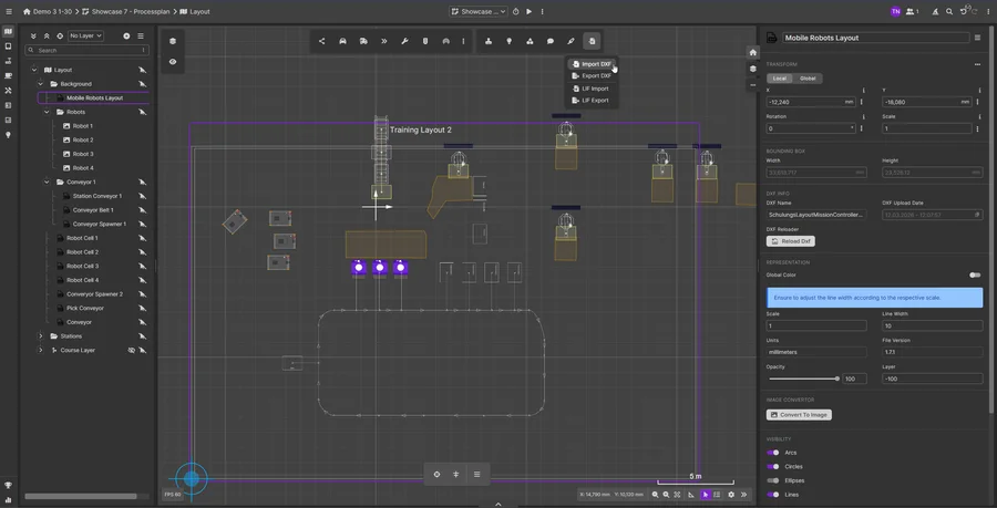
- DXF or image file import
- Scale-accurate layout import
- Multi-floor facilities
- Measurement & annotation tools
Intuitive Drawing & Commenting
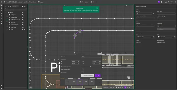
Create paths, stations, and zones via drag-and-drop. Collaborate on layouts together.
- Undo/Redo
- Grid snapping
- Copy & paste layout elements
- Multi-select & group editing
Flexible Export
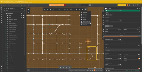
One layout, any target system. Export in the format your fleet manager needs.
- LIF standard for cross-manufacturer compatibility
- DXF export for CAD workflows
- Custom formats for specific robot manufacturers
More Editor Features
How a layout takes shape in the Editor
A project almost always starts with an existing facility floor plan. Planners import the DXF file of the facility directly into the Editor — walls, columns, racking, and gate openings load onto the canvas to scale, with no need to re-enter dimensions by hand. For multi-floor warehouses, each level can be set up as its own layer and later overlaid to check transitions at elevators or ramps.
The actual layout is built on top of this background: paths are drawn via drag-and-drop and connect automatically at intersections, stations for loading and unloading, charging points, and buffer positions are placed, and traffic zones and zone constraints mark off areas where vehicles must not occupy the same space at the same time. Each vehicle type gets a matching profile — either derived from the growing library of pre-built profiles or created from scratch using manufacturer specifications. That real vehicle envelope is then placed directly over the imported floor plan, making it visible where envelopes would collide with racking, columns, or doorways long before a vehicle is ever on site.
The Editor is used by several different roles across a project: layout planners rely on it as early as the proposal stage, to establish feasibility and rough space requirements. System integrators work in it during detailed planning, once path routing, station counts, and traffic rules need to be finalized. And customer engineers return to the same layout later, when a facility is expanded or an additional vehicle type is integrated — everyone works from the same version, without emailing files back and forth or converting between formats.
A layout is never an end product in the Editor — it's the starting point for simulation. Once paths, stations, and vehicle profiles are in place, that same data feeds directly into the simulation environment to check throughput, bottlenecks, and utilization under realistic order load. If the simulation reveals pinch points or impractical intersections, the layout is adjusted back in the Editor and simulated again — with no break between the planning tool and the testing tool.
At the end comes export: a finished layout is exported as a LIF file (Layout Interchange Format), so it can be loaded vendor-independently into practically any VDA 5050-capable fleet manager — with no rework and no need for ScaliRo to know anything about the target system. No one needs programming skills to get there: the Editor runs entirely in the browser, with no local install and no client software to maintain. Anyone who needs a project-specific export format for a particular robot vendor can add it through C#/.NET plugins, without changing anything about the core planning workflow.
FAQ
What file formats can FleetEngine Editor import?
How is a layout exported?
Can FleetEngine Editor detect collisions automatically?
Are there pre-built robot profiles?
What is LIF and why does it matter?
Try the FleetEngine Editor
Start a 30-day free trial or schedule a personal demo.