The fleet has been calculated, the robots are ordered, and in operation less arrives than planned. When we look at facilities like that, the cause often is not the robots. It is the handover station.
A handover station is any place where a load changes hands: a roller conveyor, a rack position, a lift table, a floor location. The robot drives there, picks up or sets down, and moves on. It sounds like a short event, which is exactly why many planning documents carry a single time for it. That time helps decide how many robots you need. It is almost never a single time.
In short: the cycle of the station caps throughput regardless of how many robots wait in front of it.
What a handover station is in sizing terms
A handover station is not a point in the path network but a place with a processing time and a finite capacity. It takes in one robot, holds it for the duration of the transfer and releases it again. While it is occupied, every other robot waits.
That waiting is where the calculation turns. A waiting robot does not sit in a spreadsheet, it sits in the layout: in front of the station, in an aisle, sometimes on an intersection. A capacity problem in one place becomes a traffic problem somewhere else entirely.
The robot does not grasp, it picks up and sets down
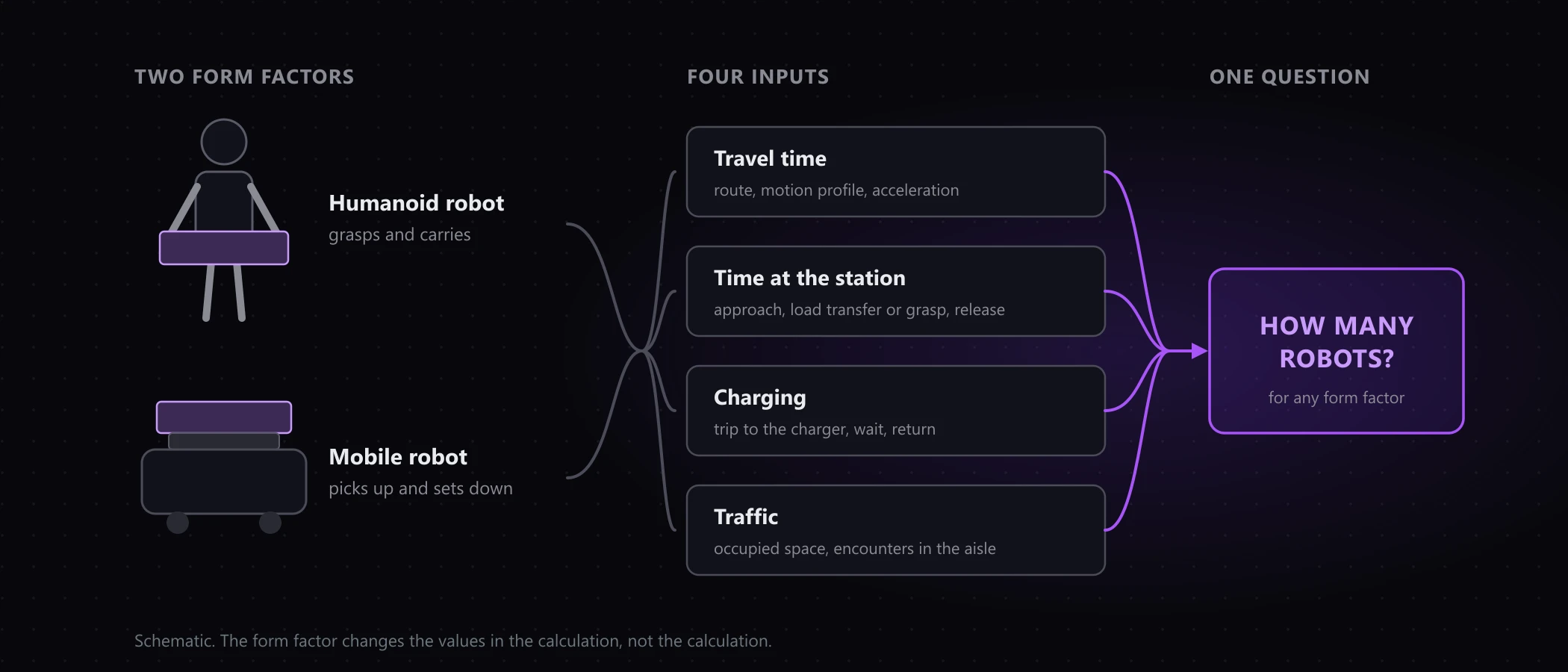
A mobile robot does not grasp. It picks up and sets down: forks under a pallet, a roller conveyor on the deck, a lift table, a hitch on a tugger. This is not a quibble about words. It is the reason the time at the station is mechanically determined and cannot be shortened by better software on the robot.
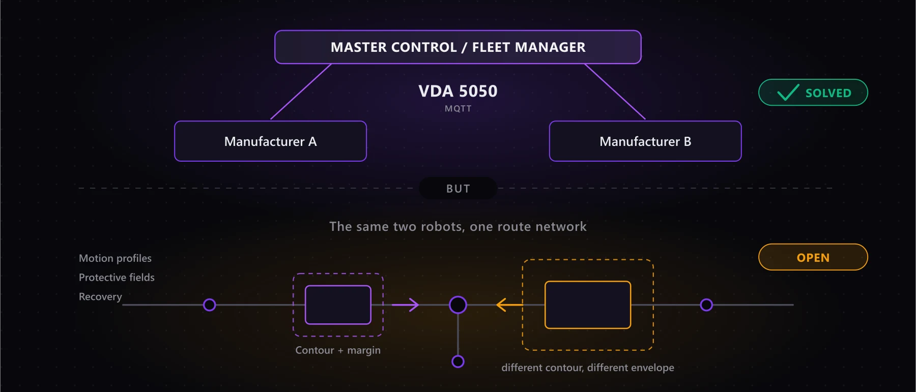
VDA 5050 models exactly that view. The standard defines the actions pick and drop, and their parameters describe the transfer rather than the robot: stationType for the design of the station, loadType for the load carrier, height for the height above the floor, side for the side the transfer happens from. Sizing a station therefore works with the same quantities that later appear in the protocol.
Three times that meet at a station
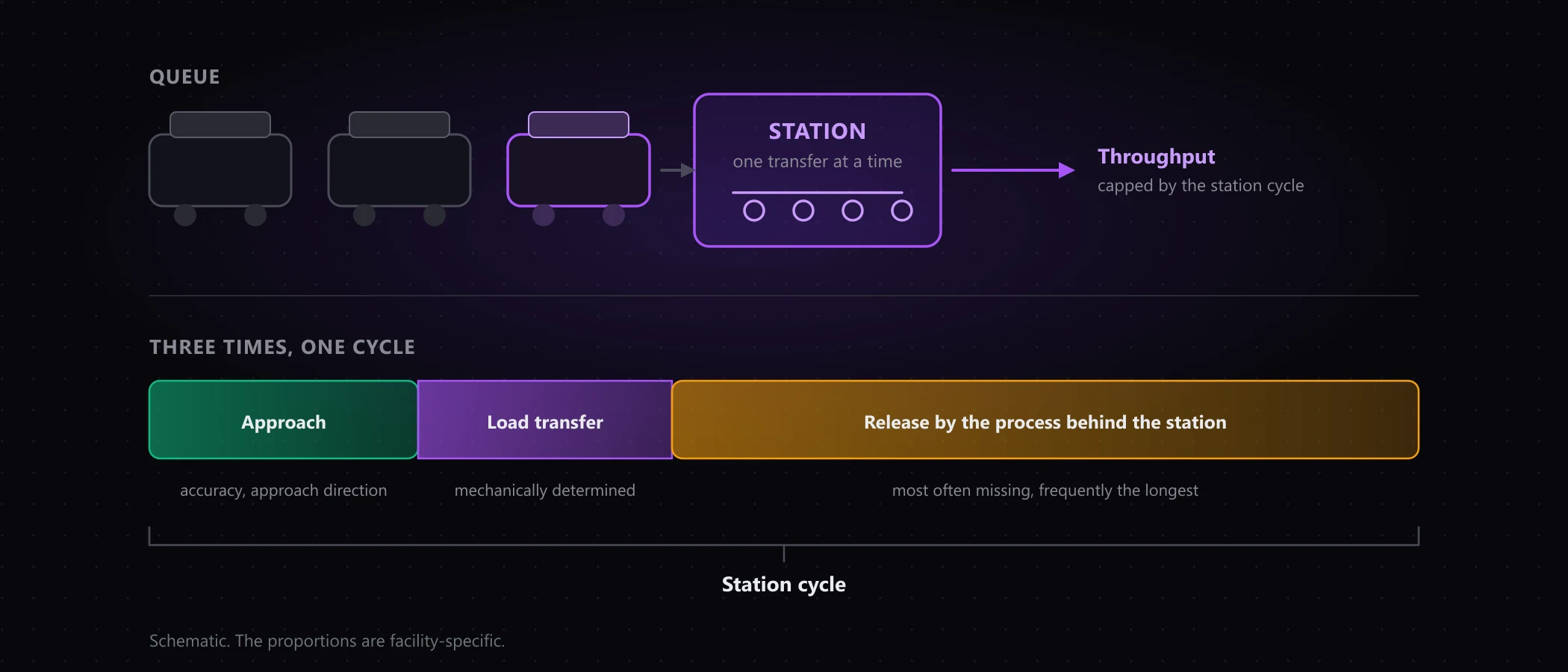
In planning conversations what I meet most often is a single number for the transfer time, carefully justified for the load exchange and with nothing before or after it. There are in fact three times:
- Approach and positioning. Depends on the accuracy the station demands and on the approach direction. A station that can only be served from one side forces detours and turns its own access route into a second constriction.
- The load transfer. Mechanically determined: lift, fork travel, conveyor run. This is the time that usually does appear in the documents, and the only one of the three that genuinely sits with the robot.
- Release by the process behind it. The time until the station can accept again. A conveyor has to clear the pallet, a machine has to finish its cycle, an operator has to confirm. This one is missing most often, and it is frequently the longest.
The third is treacherous because it does not belong to robotics and sits in someone else’s remit. It limits the fleet all the same.
Why more robots do not change the cycle
A station handles transfers one after another. Its cycle sets an upper limit, and that limit knows nothing about fleet size.
An arithmetic example, not a project figure: if a station needs 90 seconds per transfer, 40 transports pass through it per hour. Whether five robots wait in front of it or fifteen changes nothing about that. The extra robots lengthen the queue, and the queue stands in your path network.
This is the same mechanism that produces the fleet tipping point higher up in the facility, only with a cause you can name. And it compounds with the charging concept: robots driving off to charge are missing in exactly the hour the fleet was sized for.
What can be checked before you order
The levers at a station are few, and none of them is a question for the robot vendor:
- A second transfer position at the same station, so two robots can be served in parallel.
- A buffer place immediately in front of it, so the queue does not grow into the aisle.
- A shorter release time in the process behind it, often the biggest lever and the cheapest.
- A different distribution of transports across the shift, so the load peak does not land on the same station.
- The approach direction, so the access route does not become the constriction itself.
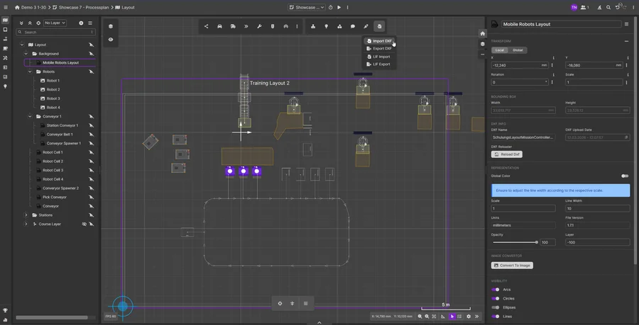
Which of these carries depends on the layout and cannot be settled by inspection. So we model stations as places with a cycle and a capacity in a graph-based model, with nodes, edges and corridors per LIF and VDA 5050, and run the facility for several days at peak load. Where a queue forms, you then see it standing in the layout instead of inferring it from an average.
The order in which robots are called to a station during live operation stays the job of your fleet management system. We complement it, we do not replace it. Our question is the one before that: does the planned cycle support the planned fleet?
What this means for your next decision
- The station belongs in the capacity equation, not in a footnote about availability.
- Three times instead of one. Approach, transfer, release. If one is missing, it is usually the longest.
- The station cycle is a hard ceiling. More robots lengthen the queue, not the throughput.
- The most effective lever often sits outside robotics, in the process behind the handover.
If an expansion or a tender is on your desk, an initial call settles in half an hour whether your handovers can carry the planned fleet. How such a sizing exercise runs is described on our planning page. Get in touch.

About the author
Tim Nowak
Tim Nowak is co-founder and Managing Director of ScaliRo GmbH. He supports operators, manufacturers and integrators with vendor-independent planning and simulation of mobile robot fleets.
LinkedIn